A Novel VTOL Aerial Vehicle
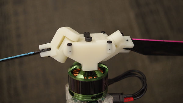
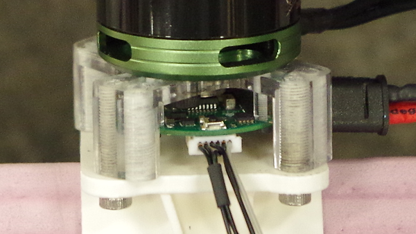
This interesting and challenging project involved the design of a novel aerial vehicle (see Figure 1). The novelty lies in its use of a unique, under-actuated rotor system that enables the vehicle to have full roll, pitch, yaw, and thrust control with only two actuators. As shown in Figure 2a, the two blades of the rotor are connected to the hub through two passive joints, one that allows each blade to move in the lead/lag direction and another that allows the blade to “flap” up and down. A custom-designed controller is connected to each motor (see Figure 2b), which takes the control signals output by the flight controller and converts them into signals that are designed to appropriately actuate the rotors.
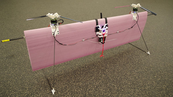
Figure 1: Dual-mode VTOL aircraft design based on a novel under-actuated rotor system.
(a)
(b)
Figure 2: Closer view of the under-actuated rotor showing: (a) center hub with passive lead/lag joints; and, (b) corresponding motor controller attached underneath.
In particular, the rotors work by responding to sinusoidal pulses from the motor. The pulses are controlled in such as way as to produce sudden bursts of torque at key points during the rotation of the corresponding propeller. Due to the weight and angular moment of inertia of the blades relative to the hub, the sudden bursts in torque result in each blade pivoting a certain amount about its respective lead/lag hinge. With the axes of these hinges being at an angle from the axis of rotation of the motor’s axle, rotation about the lead/lag hinges causes the angle of attack of each blade to change as well. This causes a differential lift between the two blades wherein the blade with the increased angle of attack produces more lift and hence pivots about the flapping hinge to lift up, while the other blade experiences a decreased angle of attack and flaps down. This differential lift happens for a brief instance in response to the instantaneous torque pulse during any given rotation of the propeller before returning to equilibrium again where both blades are level (i.e., they travel on a plane perpendicular to the axis of rotation of the motor axle). Thus, each time a differential lift occurs, a momentary torque is produce about the motor hub, which is transferred to the body of the aerial vehicle.
The custom controller is designed to precisely control the timing of these pulses in response to a given roll/pitch/yaw input from the flight controller so that the pulse happens at the same point and for the same duration of time during each rotation of the propeller. Hence, if this pulsing cycle is maintained over many rotations a net torque will be produced by the propeller. Depending on what point in the rotation of the propeller the torque pulse is applied, theoretically, a torque can be produced about any axis perpendicular to the axis of rotation of the motor shaft. In this way, a single propeller, combined with this custom controller, can produce any combination of roll, pitch, and yaw torques to control the aircraft.
In this project, two such under-actuated propellers (and corresponding controllers) were used to design a Vertical Take-Off and Landing (VTOL) aerial vehicle that could function as both a multi-rotor aircraft and as a fixed-wing airplane. The aircraft was designed as a flying wing with supports built in such a way as to allow it to take-off and land in a vertical orientation, as shown in Figure 1. The body of the aircraft was a rectangular profile wing made of pink extruded polystyrene foam (Foamular® 250, XPS), cut to have an MH45 airfoil cross-section using hot-wire foam-cutting techniques.
The PixRacer flight controller was used to receive the thrust, roll, pitch, and yaw signals from the transmitter, which were then channeled to the custom motor controllers to control the angular speed and pulsing to actuate the rotors. A 2500 6S battery powered all the electronics on the aircraft, allowing for about 5 minutes of flight.
With the two rotors capable of producing not only the necessary thrust required, but also the roll, pitch, and yaw torques, the entire aircraft was controllable using just two motors and no other control surfaces and corresponding actuators. In level flight (i.e., hover) the propeller blades maintain an equilibrium, with both rotors spinning in a horizontal plane, as can be seen in Figure 3. When a pitch input is given, sinusoidal pulsing by the motor controllers result in both rotors spinning in the same, angled plane based on the direction and magnitude of the pitch signal, as shown in Figure 4. A yaw input results in the rotors spinning in mirrored angled planes, depending again on the direction and magnitude of the yaw signal (see Figure 5). Finally, roll is achieved by increasing the thrust input on one propeller relative to the other.
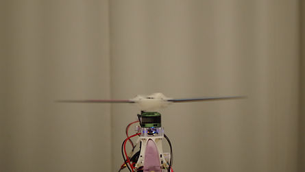
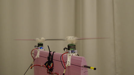
Figure 3: Rotor response in level flight (i.e., hover).
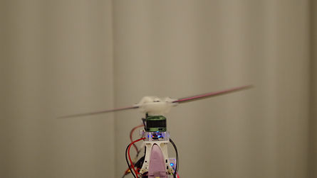
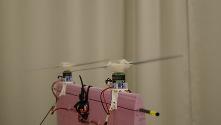
Figure 4: Rotor response to a pitch input.
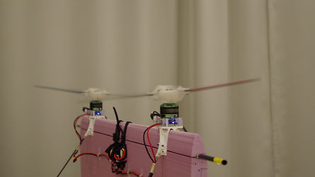
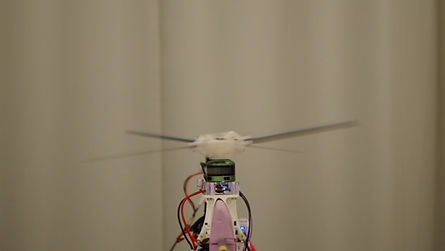
Figure 5: Rotor response to a yaw input.
Testing and experimentation with a custom-designed aerial vehicle can be precarious. On the one hand, one needs to allow the aircraft to attempt to fly unfettered in order to properly test its capabilities. However, with critical experimental hardware onboard that is both expensive and time-consuming to rebuild or replace, it is also necessary to conduct all testing in a manner that minimizes this risk. As such, it was necessary to be a little creative in testing the different designs to gauge their capabilities and gradually improve.
To test flight capability in multi-rotor mode, a tethered experiment setup was used that allowed unassisted freedom of motion to the vehicle within a fixed envelope. This was necessary in order to identify and debug issues with the mechanical design, as well as to fine-tune software parameters. The video below shows an example test within this tethered setup once a reasonably stable hover was achieved.
Video 1: Tethered hover testing.
Initial experimentation in fixed-wing flight mode was similarly challenging. The uncertainty of the behavior of the hardware components and un-tuned software parameters in this flight-mode, combined with the fact that the vehicle can quickly achieve greater distances from the pilot in this mode, meant that it was that much more important to obtain a safe and controlled means of testing. Thus, for the first few tests, a different type of tethered setup was devised, as shown in the video below. This allowed ascertaining some critical aspects of the design, including whether the wing body produced sufficient lift to allow flight given the total weight of the aircraft, whether the centre-of-gravity given the aerodynamic moments produced allowed for stable, level flight, and the impact of pitch inputs to this stability.
Video 2: Tethered forward-flight testing.
Through several design iterations of the physical structure and mechanical rotor components, as well as coding and tuning of the flight software and associated parameters, the vehicle was able to achieve a stable hover and controllable flight in multi-rotor mode. Nevertheless, the first un-tethered flight test involving performance evaluation in both flight modes ended in a crash. From the video below it can be seen that at first, a smooth and stable transition into fixed-wing flight configuration was achieved. In particular, upon acquiring a stable hover the aircraft was able to then move forward and rotate about the pitch axis until the body achieved the proper orientation to function as a wing (i.e., leading edge facing forward in the direction of travel so that the airfoil could produce lift). Unfortunately it was found that, among other things, there was insufficient roll and pitch authority to maintain controllable and level forward flight in this mode subsequent to the transition phase.
Video 3: First un-tethered flight test (a “smashing” success!).
Still, the collision was relatively mild and all critical electronics were recovered undamaged. Future work will focus on revising the design based on closer scrutiny of the flight data and the recorded video, with particular attention being given to maintaining sufficient lift, pitch stability, and controllability when maneuvering in fixed-wing flight mode.