The Labyrinth Robot
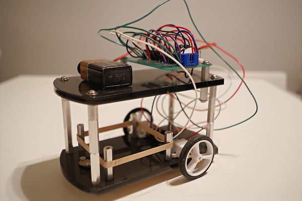
Figure 1: The “Labyrinth” robot – a differential-drive mobile robot.
In this project a manually-controlled mobile robot had to be designed that could carry a 500g payload and be driven through a maze from a pre-defined start position to a pre-defined end position, while carrying a 500g payload. The maze consisted of straight corridors with sharp, right-angled turns, necessitating careful thought toward the design to ensure that it had the required maneuverability. Hence, this project was not only an exercise in electric circuit design, but also one of effective mechanical design.
The final design also had to fit within 15-cm diameter cylinder and be no taller than 13 cm. Since solder-less breadboards were disallowed for this project, standard perfboards had to be used to implement the electrical circuitry that was designed. A handheld controller was provided that would interface the mobile robot via a six-pin ribbon cable providing, respectively, the left-motor-enable, left-motor-direction, right-motor-enable, right-motor-direction, +5V supply, and ground signals. Given the pin-out schematic of the ribbon cable connector, the mobile robot circuitry had to include a corresponding six-pin cable header jack to appropriately receive and interact with these signals. The motor-direction signals were high/low logic-levels and the motor-enable signals were pulse-width-modulated digital signals that could vary from 0% (indicating stop) to 100% (indicating full speed). A selection of motors with different gear-ratios was provided from which the set of actuators for the design had to be chosen.
The final design was a differential drive mobile robot with a castor serving as the third wheel to provide balance and stability. The body was composed of laser-cut acrylic plates stacked and connected together using hex spacers in such a way as to provide mounting points for the motors, a secure area for the payload, and an easily-accessible surface onto which the perfboard containing the main circuitry could be attached. The circuit design consisted of a quadruple half-H driver combined with HEX inverters, and wired with the two motors in such a way as to ensure that identical PWM left and right motor-enable input signals caused the diametrically opposed motors to spin in opposite directions (resulting in straight forward or backward motion of the mobile robot). Moreover the driver was able to use these PWM signals to switch the corresponding motors on and off at the correct frequency to effectively control their rotational speed. The power supply for the overall system was a 9V battery that directly powers the two motors, but is passed through a 5V voltage regulator to power the motor driver and the controller. This design successfully completed the maze challenge, proving to be easy to control via the handheld controller and navigating through the narrow corridors and tight turns without issue.