The "Stalker"
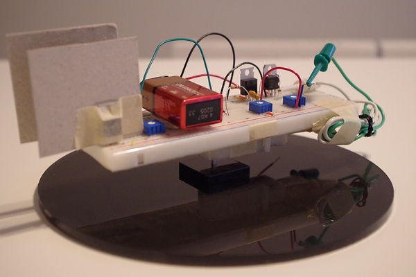
Figure 1: The “Stalker” – an autonomous, infrared-beacon-tracking robot.
The “Stalker” project required the design of an autonomous, rotary, infrared-light-seeking system, using readily-available, off-the-shelf, discrete electronic hardware components. The device needed to track an infrared beacon, positioned anywhere within a range of 50cm to 90cm away, over a 180° arc. In addition to electronic components, an electric motor was also provided to drive the system. Moreover, the system had to incorporate a red dot laser diode module that would point in the direction of the infrared beacon. The vertical alignment of the red dot from the laser relative to the LED beacon was used to determine the accuracy of the device. The entire design had to fit within a 20cm diameter cylinder.
The circuitry needed to achieve these objectives was built on top of a breadboard, which not only kept the overall design within the size constraints, but also expedited prototyping, testing, and making design revisions by not requiring soldering/de-soldering of components. In the final design, a phototransistor was mounted at one end of the breadboard, pointed outward, as shown in the picture. A MOSFET, triggered by the current-flow produced when the phototransistor senses incoming light from the LED beacon, is used as a switch to turn a motor on or off. The motor body was attached underneath the breadboard, with its axle aligned vertically, perpendicular to the bottom surface of the breadboard. The axle, in turn, was fixed into a 3D-printed base that was mounted onto the table.
The circuit was setup in such a way that when no light is sensed, the motor is ON, thereby rotating the breadboard (and, thus, the phototransistor on it) counterclockwise, resulting in the device effectively “seeking” the LED beacon. As soon as the phototransistor was aligned with the beacon, it began to receive incoming infrared light, thereby turning the motor OFF, leaving the phototransistor aligned with the LED beacon. Mounted on the bottom of the breadboard, just underneath the phototransistor (not shown in the image) was a 30mA (at 3V) red dot laser diode. The entire circuit was powered by a standard 9V battery. The cardboard barriers placed on either side of the phototransistor helped to limit its angular range of detection, thereby preventing premature stopping of the motor and helping to ensure better, more accurate alignment with the LED beacon.